


Products
Product information
[Basic Knowledge about Cryopumps 4 ]
Performance Characteristics
The essential performance characteristics for cryopump operation are: ①Cooldown, ②Pumping Speed, ③Pumping Capacity, ④Maximum Throughput, ⑤Crossover Pressure, ⑥Ultimate Pressure, and ⑦Thermal Load Capacity. For details, see each section below.
1.Cooldown Characteristics
The vacuum chamber must be rough pumped before cryopumping since cryopumps cannot start its operation from atmospheric pressure. When rough pumping a CRYO-U® cryopump with a rotary pump, roughing pressure of 40Pa is sufficient since backflow of oil vapor will not occur. The residual gas will be adsorbed to adsorbent inside cryopump.
Cooldown time differs depending on conditions as shown in table below.
Table 1.Factors which affects Cooldown Time
| Factor | Condition | Cooldown Time |
| 1.Rough Pumping Pressure | HIGH | Extended |
| 2.Pump Temperature | HIGH | Extended |
| 3.Residual Gas Composition After Rough Pumping |
DRY(Dry inside cryopump) | Extended |
| WATERY | Shortened | |
| 4.Contamination of Cryopump | CONTAMINATED | Extended |
Cooldown time is affected by regeneration method. Use of N2 purge or Band Heater may extend the cooldown time causing temperature rise, or dry condition which hardly achieves vacuum insulation. Also, slight leakage may cause extended cooldown time or cooldown failure.(Especially due to leakage from pressure relief valve.) Cooldown time may be reduced by 10 to 15% at 60Hz compared to that at 50Hz.
Generally, cooldown time is defined as the amount of time for 15K cryopanel temperature to drop to 20K or below. See Table 2 for details.
2.Pumping Speed Characteristic
2-1.Pumping Speed for Water
It is usually assumed that the water condensation probability on cryosurface is approx. one, provided that the cryosurface temperature is below 150K. In normal operation, temperature of 80K shield and baffle is below 130K(80K or below in normal use). Therefore the pumping speed for water is equivalent to ideal pumping speed of cryopump which has a diameter of 80K shield. The ideal pumping speed (s) per unit area for molecular weight M is given by:
s=62.5/M1 / 2(L/s/cm2)(20℃)
Water molecular weight M is 18, thereby the ideal pumping speed(s) is 14.7(L/s・cm2).
Pumping speed for water(S) is given by S=s・A(L/s), provided the area of 80K shield inlet is A(cm2).
For 8-inch cryopump, the area of 80K shield inlet is approx. 275cm2, thus, the pumping speed for water is 4000L/s. The same calculation is available for gases condensed and pumped on 80K baffle such as CO2 and NH4 etc.
CRYO-U8H pumping speed for water is 4000L/s. Since molecular weight of CO2 is 44, CRYO-U8H pumping speed for CO2 is given by:
SCO2=SH2O× (18/44)1/2=2560L/s
As you see, the capture probability(sticking coefficient) of condensing array for condensable gases is one, provided the temperature of cryosurface is below 20K. Also, cryopump pumping speed at molecular flow region is constant since the conductance from inlet to cryopanel is constant at molecular flow region.
The speed values given in brochures are pumping speed for nitrogen at molecular flow region. Pumping speed for condensable gases of molecular weight M other than nitrogen can be calculated by following equations.
SM=SN2×(28/M)2/1(L/s)
Table 2.Pumping Speed of Various Cryopump for Nitrogen(Value from Brochure)
| Diameter | Model | Pumping Speed(L/s) |
| 6 | U6H | 2100 |
| 8 | U8H,U8H-U,U8HSP | 4000 |
| 10 | U10PU | 6900 |
| 12 | U12H,U12H-K2,U12HSP | 9500 |
| 16 | U16,U16P | 16000 |
| 20 | U20P | 29000 |
| 22 | U22H | 39000 |
| 30 | U30H | 70000 |
2-2.Pumping Characteristic for Argon and Nitrogen (Condensable Gas)
A group of gases such as N2、Ar、CO、O2 and other gases of similar molecular weight are condensed and pumped at 20K or below, therefore they are not condensed on 80K baffle and shield. In general, the limit temperature that gases can be pumped by condensation is 20K. The temperature of condensing array when condensation probability of gases becomes below one at 300K is:
N2 :approx. 23K
Ar :approx. 27K
Also, the temperature when cryopump loses its pumping ability is:
N2 :approx. 27K
Ar :approx. 29K
As you see, the capture probability(sticking coefficient) of condensing array for condensable gases is one, provided the temperature of cryosurface is below 20K. Also, cryopump pumping speed at molecular flow region is constant since the conductance from inlet to cryopanel is constant at molecular flow region.
The speed values given in brochures are pumping speed for nitrogen at molecular flow region. Pumping speed for condensable gases of molecular weight M other than nitrogen can be calculated by following equations.
SM=SN2×(28/M)1/ 2(L/s)・・・・・・・(1)
SN
2:Pumping Speed for Nitrogen(L/s)
For example, CRYO-U8H pumping speed for argon is (See Table 2):
SN2=1700(L/s)and also molecular weight of argon is 40, thus, the calculation is:
Sar=1700X(28/40)1 / 2=1400L/s
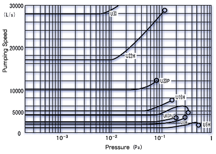
Figure 1.CRYO-U Pumping Speed for Nitrogen
| Model | Pumping Speed(L/s) |
| U6H | 750 |
| U8H/U8H-U/U8HSP | 1700 |
| U10P | 2300 |
| U12H | 4000 |
| U12HSP | 4100 |
| U16/U16P | 5000 |
| U20P | 10000 |
| U22H | 17000 |
| U30H | 28000 |
Table 3.Pumping Speed of Various Cryopump for Nitrogen(Value from Brochure)
When gas flow changes from molecular flow to intermediate flow(transition flow), pumping speed increases since the conductance increases proportional to the pressure. However, since incoming heat increases as pressure increases, cryopump reaches its limit of pumping ability when the thermal load exceeds cold head refrigerating capacity. ULVAC CRYOGENICS defines the flow rate when the cryopanel reaches 20K by the thermal load as the maximum throughput.(The point marked “○” in Figure 2.) The maximum throughput may be increased with large refrigerating capacity, but it may generate temperature gradient in thickness direction since the thermal conductivity for cryoarray is limited even with a large refrigerating capacity. If the temperature of condensation array becomes too high exceeding its limit, gases will not be condensed, and then pumping capacity becomes zero. That is to say a physical limit of pumping.
2-3.Pumping Speed for Hydrogen, Helium, and Neon(Non-condensable Gas)
The next group of gases such as hydrogen, helium, and neon will not condense at 20K and will not be pumped efficiently by metal surface because the equilibrium vapor pressure for cryosorption will be too high. These gases cannot be pumped through condensation, therefore adsorbent cooled below 20K is provided to adsorb these gases. The pumping speed will decrease as the surface coverage increases. When the pumping speed is down to 80% of its starting value, the total amount of pumped gases is defined as the pumping capacity. (see below.) Pumping speed for non-condensable gases depends on the following:
(1)Adsorption Probability of Adsorbent Influenced Factors Below.
①Characteristics, Installation Method, and Configuration of Adsorbent
②Temperature and Amount of Adsorbent
③Rate of Degassing
④Kinds and Amount of Gases Previously Adsorbed
⑤Flow Rate and Temperature of Gases
(2)Arrival Rate of Gas from Inlet to Adsorbent (Conductance)
Typically the pumping speed is determined in accordance with test results. Pumping speed for gases with large amount of adsorption such as hydrogen and neon is constant at molecular flow region. Temperature of cryopanel rises as gas flow rate increases, and the flow rate at 20K is defined as the maximum throughput. For non-condensable gases, pumping at the maximum throughput or around may be performed for a short time because the adsorption probability decreases in a short time with increasing the amount of non-condensable gases adsorbed to the adsorbent. In case of pumping hydrogen at high flow rate, it is advisable to operate intermittently rather than continuously to maintain its pumping capacity.
Hydrogen, one of non-condensable gases, is not only a component of outgas but also vital for application, therefore specifications are determined in detail. There is few data for neon because it is not used in common. Also, for helium which is hardly likely adsorbed, it is not recommended to pump them by cryosorption since they can be pumped about 1% to 0.1% of hydrogen.
| Model CRYO-U |
Pumping Speed
(L/s) |
Maximum Throughput
(Pa・L/s) |
Pumping Capacity
(Pa・L) |
| -U6H | 1100 | 1.1×10² | 3.1×10⁵ |
| -U8H | 2700 | 2.4×10² | 1.0×10⁶ |
| -U8HSP | 3200 | 2.4×10² | 1.0×10⁶ |
| -U10PU | 3600 | 1.5×10² | 6.7×10⁵ |
| -U12H | 6000 | 4.1×10² | 9.8×10⁵ |
| -U12HSP | 6000 | 4.1×10² | 1.6×10⁶ |
| -U16 | 10000 | 4.1×10² | 2.4×10⁶ |
| -U16P | 10000 | 4.5×10² | 2.4×10⁶ |
| -U20P | 18000 | 5.0×10² | 4.6×10⁶ |
| -U22H | 25000 | 1.3×10³ | 8.5×10⁶ |
| -U30H | 43000 | 7.4×10² | 1.5×10⁷ |
Table 4.CRYO-U Pumping Performance for Hydrogen
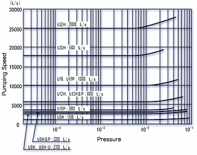
Figure 2.CRYO-U Pumping Speed for Hydrogen
3.Pumping Capacity of Cryopumps
Since a cryopump does not have a continuously functioning exhaust port, it has a limiting value of pumping. That is called the pumping capacity. When a cryopump becomes saturated, it is required to be regenerated because the performance degradation such as ultimate pressure rise and lowered pumping speed will occur. There is a big difference of cryopump pumping capacity between non-condensable gases and condensable gases. For instance, the pumping capacity for hydrogen is about 1% of that for nitrogen and argon.
3-1.Pumping Capacity for Condensable Gases
The gases pumped by condensation are ①gases pumped at 80K shield and baffle (mainly H2O) and ②gases pumped at 15K cryopanel (nitrogen, argon, oxygen, etc.)
(1)Pumping Capacity for Water
The pumping speed for gases condensed or adsorbed at 15K cryopanel decreases as the accumulated water frost deposit reduces their conductance by making the gas passages in the pump narrower. When the pumping speed significantly lowered, regeneration is required. There is no clear definition of the pumping speed for water, but it is assumed that the pumped water before regeneration is the pumping capacity for water. Refer to table below for pumping capacity for water.(Note that the unit is in grams(g).)
| Model | Pumping Capacity (g) |
| CRYO-U6H | 40 |
| CRYO-U8H,U8H-U | 90 |
| CRYO-U10PU | 170 |
| CRYO-U12H | 260 |
| CRYO-U16,U16P | 500 |
| CRYO-U20P | 1000 |
| CRYO-U22H | 1400 |
Table 5.Pumping Capacity for Water(as measure)
| (1)Materials which release much water during processing are: |
| Plastic |
| Glass |
| Ceramic |
| (2)Cautions for regeneration at atmosphere with much water are: |
| Melt ice completely when warming up. |
| Do not freeze water when rough pumping. |
| Remove water from inside cryopump completely. |
| Confirm the operation of rotary pump.(Avoid emulsifying of oil.) |
(2) Pumping Capacity for Argon
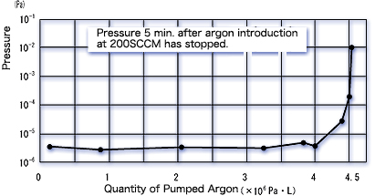
In sputtering process, there is a problem concerning the pumping capacity for argon condensed at 15K cryopanel. If the accumulated argon frost on the external surface of 15K cryopanel becomes thick, it may reach 80K baffle and shield which are both high temperature parts compared to 15K cryopanel. In addition, there is a possibility of insufficient pumping for argon since the temperature of argon frost reached to 80K baffle and shield may become too high to condense argon more than that. The amount of argon, which is pumped previously until then, is called the pumping capacity for argon. Pumping capacity for argon is defined as the amount of previously pumped argon when introduction of argon has stopped, and the pressure after 5 minutes with closing main valve does not drop below 1.3X10⁻⁴Pa. Even if the introduction of argon is stopped, the pumping ability will be lost if the pumping capacity for argon has reached its capacity. Figure 3 shows the pressure build up of CRYO-U12HSP. In this figure, argon has been introduced continuously at 200SCCM, and then the pressure 5 minutes after the introduction of argon has stopped was recorded. As you see from the figure, the pressure buildup worsens significantly at 4.3X10⁸ Pa・L, and thus it is assumed that the pumping capacity is 4.3X10⁸ Pa・L. Various cryopump pumping capacity for argon is also shown in Table 6.
Figure 3.Pressure Buildup of CRYO-U®12HSP(Example)
| ModelCRYO- | Pumping Capacity(Pa・L) |
| -U6H | 5.6×10⁷ |
| -U8H,U8H-U | 1.0×10⁸ |
| -U8HSP | 2.5×10⁸ |
| -U10PU | 1.0×10⁸ |
| -U12H | 2.1×10⁸ |
| -U12HSP | 4.3×10⁸ |
| -U16,U16P | 4.3×10⁸ |
| -U20P | 5.8×10⁸ |
| -U22H | 8.1×10⁸ |
| -U30H | 7.8×10⁸ |
NOTE: Pumping capacity for N2 is approx. equal to the value above divided by 1.3.
Table 6:Pumping Capacity for Argon
3-2.Pumping Capacity for Non-condensable Gases
Non-condensable gases such as hydrogen, helium, and neon are pumped by porous materials attached to inner surface of 15K cryopanel since they will not condense at 10K and will not pumped by the metal surface. Therefore, not only will the capacity be limited to fractions of a monolayer, but the pumping speed will decrease as the surface coverage increases, and the cryopump will lose its pumping ability at last. When the pumping speed for hydrogen drops to 80% of its starting value, ULVAC CRYOGENICS defined the quantity of hydrogen pumped as the pumping capacity for hydrogen. The adsorbent should be kept clean to attain its adsorption ability. Contamination of adsorbent is caused by:
① Adsorption of condensable gas such as air.
② Adsorption of water
③ Adsorption of oil vapor
Adsorption ability may be decreased by adsorbing large quantity of substances above. Air and water can be removed from cryopumps by regeneration while oil vapor cannot. If oil vapor is adsorbed to 15K cryopanel(Adsorption panel), the panel is required to be exchanged. Thus, avoid backflow of oil vapor to the cryopump to maintain its pumping ability for hydrogen.
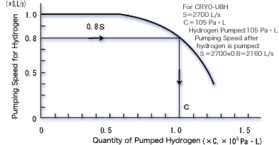
Figure 6-5 shows pumping speed for hydrogen and quantity of pumped hydrogen. In this figure, “S” represents pumping speed and “C” represents pumping capacity. Refer to Table 6-4 for various cryopumps pumping speed and capacity for hydrogen.
Figure4.Pumping Speed and Pumping Capacity for Hydrogen
4.Thermal Load and Maximum Throughput
The thermal load to cryopumps is generated not only by heat radiation from the equipment, but also heat from gases such as thermal conductance or heat transfer with condensation. They are given by the following equations:
![]()
| σ | :Boltzmann constant 5.67×10⁻¹²W/cm2/K4 |
| εAV | :Mean Radiation Rate |
| T1 | :Low Temperature Surface(K) |
| T2 | :High Temperature Surface(K) |
| A | :Heat Receiving Area(cm2) |
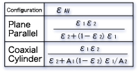
A1:Inside A2:Outside
![]()
| γ | :Specific Heat Ratio |
| a0 | :Mean Thermal Accommodation Coefficient |
| P | :Pressure(Pa) |
| M | :Molecular Weight |
| T1 | :Low Temperature Surface(K) |
| T2 | :High Temperature Surface(K) |
| A | :Heat Receiving Area(cm2) |
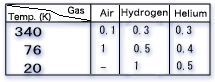
Mean Thermal Accommodation Coefficient a0(A1<A2)
![]()
Accommodation Coefficient a1,a2 (approx.)
![]()
| γ | :Condensation Heat(Adsorption Heat for H2, He, and Ne) (W/Pa・L/s) |
| Tc | :Low Temperature Surface(K) |
| Tg | :Gas Temperature(K) |
| S | :Cryopump Pumping Speed(L/s) SP:(Pa・L/s) |
| P | :Pressure(Torr) |
| Cp | :Mean Specific Heat of Gas(W/(Pa・L/s)/K) |
Thermal load to 1st stage of cold head is from radiation heat and heat conduction of gases, but mainly from radiation heat in normal use except for continuous operation at the same level of 10-1Pa. Thermal load to 2nd stage of cold head is from gas condensation heat, and the maximum throughput is depending on it. The maximum throughput may be reduced as the thermal load to 1st stage increases since the thermal load to 1st stage affects the refrigerating capacity of 2nd stage.
Thus, in case that a large amount of gas is introduced into a cryopump, keep the cryopump clean to avoid radiation heat and also to reduce the thermal load. Generally, a large cryopump requires refrigerators with high-performance refrigerating capacity because thermal load coming from a large inlet is heavy.
The cryopump maximum throughput is defined as the flow rate when temperature of cryopanel becomes 20K under normal radiation heat. In case of cryopumps which have the same sized inlets, the maximum throughput increases as refrigerating capacity increases, or pumping speed increases. For instance, the maximum throughput for CRYO-U16P with R50(cold head) is bigger than that of CRYO-U16 with R20(cold head) because the refrigerating capacity of R50 is bigger than that of R20.
The cryopump maximum working pressure Pmax is given by:
Pmax = Qmax ÷ Smax
Qmax: Maximum Throughput Smax: Pumping Speed
Pmax for argon is in the 10-1Pa, intermediate flow.
The maximum throughput for various cryopumps are shown in Table.
Cryopump Maximum Throughput
| Argon (Pa・L/s) |
Hydrogen (Pa・L/s) |
|
| CRYO-U6H | 1.1×10³ | 1.1×10² |
| CRYO-U8H,U8H-U,U8HSP | 1.2×10³ | 2.4×10² |
| CRYO-U10PU | 8.0×10² | 1.5×10² |
| CRYO-U12H,U12HSP | 2.0×10³ | 4.1×10² |
| CRYO-U16 | 1.4×10³ | 4.1×10² |
| CRYO-U16P | 1.6×10³ | 4.5×10² |
| CRYO-U20P | 1.1×10³ | 5.0×10² |
| CRYO-U22H | 4.1×10³ | 1.3×10³ |
| CRYO-U30H | 2.7×10³ | 7.4×10² |
5.Crossover
Crossover is defined as the pressure inside the vacuum chamber(roughing pressure) when switching from rough pumping to cryopumping by opening the main valve. The maximum permissible roughing pressure is called the maximum permissible crossover pressure. Cryopumps start pumping operation with opening the main valve, and after pumping a certain amount of gases they are required to be regenerated by warming up and discharging pumped gases. The maximum permissible crossover pressure is given by:
![]()
The maximum amount of gas which can be pumped should be a evacuation limit value for cryopumps to recover the pumping ability (in general, temperature of cryopanel is over 20K). However, for safety reasons, the actual maximum permissible cryossover pressure is a half of the value given by the calculation above. In addition, if you take more safety measures, the maximum permissible crossover pressure should be within the value before the temperature of cryopanel exceeds 20K. The maximum amount of gas which can be pumped is depending on the thermal load to cryopump and amount of gases condensed inside cryopump.
Use Table 6-8 as a measuring of the maximum amount of gas pumped for air.
For example, in case of U8H, the maximum permissible crossover pressure(Pmax) for a vacuum chamber of 100L is:
Pmax ≦133000Pa・L/100L=1330Pa
Thus, the roughing pressure is below 1330Pa. For safety reasons, it shall be 665Pa.
For more safety measures(not to exceed 20K), take the value on the right column, then:
P= 20000/100 =200Pa
In case of large volume of chamber and roughing pressure of 40Pa or below, take special measures such as prevention of oil backflow, use of large cryopumps, and use of additional cryopumps to keep roughing pressure at 40Pa or more.
6.Ultimate Pressure
When there is no incoming gas into cryopump, the ultimate pressure for condensable gases is given by the vapor pressure and condensation coefficient(hypothetically 1 in here) for each gas as follows:
Pg=Ps(Tg/Ts)1/2
| Ts | :Temperature of Cryosurface 10~20K |
| Ps | :Vapor Pressure at Temperature(Ts)(Mean Adsorption Pressure for H2)(Pa) |
| Tg | :Temperature of Gas ~300K |
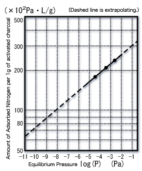
| Figure 6-6 shows the ultimate pressure for nitrogen at 10 to 20K. In this figure, nitrogen is chosen because the vapor pressure of nitrogen has the highest vapor pressure among the condensable gases. Generally, temperature of cryopanel drops to 10 to 12K or around without thermal load. Thus, we can ignore the adsorption equilibrium pressure(Pa) from a practical point because pressure from vapor pressure is below 20-21Pa. The ultimate pressure for hydrogen, non-condensable gas, is depending on the mean adsorption pressure. As you see in Figure 6-7, the activated charcoal attached to cryopumps has high adsorption ability for hydrogen. In addition, you may ignore the mean adsorption pressure(Pa) for hydrogen since the amount of pumped hydrogen is very little in ultra-high vacuum atmosphere. For example, When operating U8H(SH2O=2700 L/s) at 1.3X10⁻⁸Pa for one month, the amount of hydrogen adsorbed is : Q=1.3x10-8x2700x30x24x3600=91Pa・L Therefore, the ultimate pressure of cryopump is determined by balancing with the amount of incoming gases and pumping speed of cryopumps. Generally, the ultimate pressure is measured with closing cryopump by a blank flange to minimize the amount of the incoming gas. In addition, the ultimate pressure differs widely according to the specifications(for normal use and ultra-high vacuum use), roughing pressure, and operation with or without baking. When rough pumping to 40Pa with standard O-ring sealing, and no-baking, the ultimate pressure after approx. 12 hours will be (1~4)X10-6Pa. Figure 6-7 shows a test result of the residual gas compositions after baking and without baking. Also, Table 6-9 shows the estimation of ultimate pressure for a cryopump. After baking completely, cryopumps can attain ultra-high vacuum atmosphere around 10-10Pa with ultra-high vacuum specifications. The ultimate pressure of the system is depending on outgas from the system.(P=Q/S) |
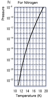
Figure 6.Ultimate Pressure |
Adsorption Isotherm of Acctivated Charcoal for H2
Cryopump Ultimate Pressure(Estimation)
| TYPE | Roughing Pressure(Pa) | Baking | Ultimate Pressure(Pa) |
| Standard | 40 40 |
- (100~150℃)×(3~10h) |
(1~4)×10-6 (1~4)×10-7 |
| Ultra-high Vacuum |
10-2~10-3 10-2~10-4 10-2~10-3 |
- (200~220℃)×(3~8h) (200~220℃)×約20h |
10-8 10-9 10-10 |
Please feel free to contact us about our product.
Our consultants will propose plans that fit your needs.