


Products
Product information
[Basic Knowledge about Cryopumps 2 ]
INSTALLATION AND OPERATRION
1.Installation of Cryopumps
CRYO-U Cryopumps can be attached in any position since small-type helium refrigerator is used, except for CRYO-U30 and U22. However, it is preferable to use a cryopump in the same direction to prevent seal abrasion. For Hydrogen Vapor Pressure Gauge, position cryopumps at proper location to monitor the pressure gauge without difficulty. Compressor units must be set up on a level floor(±5°) where can monitor the pressure gauge of compressor units.
Cryopumps and compressor units need enough space around for the maintenance service. For air-cooling type compressor units, ensure space over 30cm for front and back not to block flow of air. Also, check the heat exchanger(radiator) periodically to make sure there is no refuse.
Flexible hose should not be forcibly bent at right angle because bending at an acute angle may cause helium leakage. Be sure that the minimum bending radius is 250mm for flexible hoses. If necessary, use flexible hose with L-type metal fitting, or elbow joint.
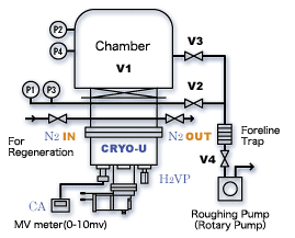
Typical diagram of cryopump system is shown in Figure 1.
If the roughing pressure is over 40Pa, the foreline trap in the Figure 1 is not required because back-flow of oil vapor will not occur. If foreline trap is used, it requires regeneration of foreline trap itself occasionally.
If a dry pump is used, it can rough pump up to its performance capacity because back-flow of oil vapor will not occur. In general, an ionization vacuum gauge is not required, but it is recommended to install to check the ultimate pressure.
When pumping a large amount of H2O, consider outlet for liquid water in advance.
| Figure 1:Typical Diagram of Cryopump System | |||||||||||||||||
 |
|
||||||||||||||||
2.Isolation and Shielding from Heat Source
Refrigeration capacity of cryopumps differs according to the model, however it may be several tens of watts at 80K for 1st stage, and several watts at 20K for 2nd stage. At the same time, there are heat sources such as vapor source and heater in a vacuum chamber.
Radiation heat from 254mm inlet diameter surface(10 inch-cryopump) is shown in Figure 2.
As you see, the radiation heat increases as the temperature and radiation rate increase.
Since the heat generated in a chamber goes far beyond the refrigeration capacity of cryopumps, if there is direct incoming radiation, the cryopump will lose its pumping ability.Therefore, cryopumps must be shielded from any heat source in a chamber to maintain its refrigeration capacity.
Figure 2:Radiation Heat from φ254mm Inlet Radiation Rate and Temperature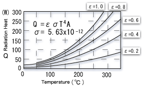 |
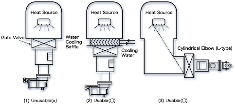
Some installation reference examples are shown in Figure 3. As you see, example (1) is unusable because the inlet of the cryopump faces to the heat source directly.
Example (2) and (3) are usable, but requires to consider incoming radiation by reflection in case the heat source has extremely high temperature.。
Figure 3:Installation Examples
<The heat load of radiation heat to cryopumps is given by:>
Q=εAV・σ・A・(Tw4-T14) (W)
εAV:Average Radiation Rate,σ:Boltzmann Constant=5.67X10⁻¹²(W/cm2/K4),A:Heat Receiving Area(cm2)
Tw:Chamber Wall Temperature(normally 300K), T1:Temperature of Shield and Baffle(normally 80K)
3.Cooling Water(Flow Rate and Quality)
The heat generated by input power to compressor unit can be water cooled or air cooled. In air-cooling system, the heat is removed by air-cooling fan and heat exchanger(radiator). Air-cooling system can reduce the running cost since it does not require cooling water and also extra piping work. However, water-cooling method is becoming more popular lately because air-cooling method requires air-conditioning for removing heat released , and also it may cause noise and dust.
In water-cooling system, there is a possibility of difficulty in start-up, or overload of compressor unit because oil inside compressor unit may be thickened by cold cooling water. On the other hand, high temperature cooling water or poor cooling water may cause overheat or cooling failure, and stop the compressor operation. Therefore, be sure to satisfy all requirements described in the manual for proper cooling water flow rate and qualities. If the cooling water temperature is below 10℃, be sure to stop the water flow as the compressor unit has stopped. This is also one of the preventive measures against difficulty in star-up. Also, freezing of cooling water may cause pipe rupturing, therefore be sure to drain residual water inside the compressor unit by blowing air.
Cooling water shall be clear and pure without water stain and scale. Poor quality water may decrease the flow rate and heat transfer effect clogging the pipe line. Also, the use of poor quality water which may cause piping to corrode may result in a serious accident by generating a pinhole of heat exchanger. ULVAC CRYOGENICS employs water standards provided by The Japan Refrigeration and Air-conditioning Industry Association as our cooling water standards to ensure reliable performance of heat exchanger. It is recommended to make regular examinations of the water and pipe cleaning because always there is a possibility of temporary water degradation.
Table 1:Cooling Water Standard Quality
| Item | General Standard |
Recommended Value for Cryopumps |
Characteristic | ||
| Corrosion | Scaling | ||||
| Standard Item |
pH (25℃) | 6.5~8.0 | 6.5~8.0 | ○ | ○ |
| Electric conductivity(25℃) (μ S/cm) | 800以下 | 200以下 | ○ | ○ | |
| Chloride ion Cl- Cl- (mg Cl-/L) | 200以下 | 50以下 | ○ | ||
| Sulfuric acid ion SO2-- (mg Cl-/L) | 200以下 | 50以下 | ○ | ||
Note: ○ shows the potential factor for corrosion or scaling.
4.Cryopump Operation
There are three processes in cryopump operation as follows.
(1) Start Up Rough Pumping and Cooldown
(2) Normal Operation Cryopump Pumping Operation
(3) Shutdown, Regeneration Stop and Regeneration
1.Start Up(Rough Pumping and Cooldown)
Start the cryopump operation as follows.
(1)Turn ON the main power.
(2)Circulate cooling water for water-cooling type compressor unit.
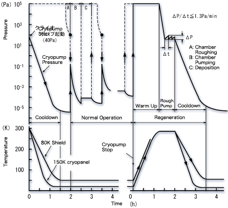
(3)Rough pump inside the cryopump to 40Pa.(Do not rough pump to 13 to 20Pa or below because it may cause oil contamination by oil backflow of rotary pump. Rough pumping utilizing dry pump has no such a oil trouble, therefore cryopumps can be rough pumped to several Pa.)Generally, pressure build-up test is performed at this point.
The recommended limit value of pressure build-up speed is: ΔP/Δt≦1.3Pa/min
(4)Start the cryopump operation.
(5)Wait until the condition is ready for cryopump operation.
The condition is considered to be ready when:
●15K cryopanel temperature drops below 20K.
●80K shield temperature drops below 130K.
(Electro motive force of K thermocouple is –5.5mV)
Cooldown time to reach required cryogenic temperature differs according to models of cryopumps as shown in Table 4-2.
(6)When the condition is ready, start normal cryopump operation.
Table2:Cooldown Time for Various Cryopumps(Rough Pumping:40Pa)
| Model | U6H | U8H | U8HSP | U10PU | U12H | U12HSP | U16 | U16P | U20P | U22H | U30H | |
| Cooldown Time (min.) |
50Hz | 80 | 100 | 110 | 150 | 85 | 90 | 110 | 120 | 160 | 150 | 240 |
| 60Hz | 70 | 90 | 100 | 135 | 75 | 80 | 100 | 110 | 140 | 135 | 200 | |
NOTE: Cooldown time may be extended when inside cryopump is contaminated, thermal load is heavy, inside cryopump is completely dry by regeneration, and Helium, Hydrogen, and Neon is included more than approx. 0.1Pa at partial pressure in the residual gas after rough pumping.
CRYO-U12Hの運転サイクル例
2.Normal Operation
When the condition is ready for cryopump operation, start cryopumping as follows.
(1)Rough pump the vacuum chamber below maximum allowable crossover pressure(See Sec. 6.5). Generally, 40Pa is common for rough pumping pressure. However, if rotary pump is used as roughing pump, do not rough pump the chamber below 13Pa to prevent oil backflow from rotary pump. Meanwhile, if dry pump is used as roughing pump, the chamber can be rough pumped below 13Pa without any trouble.
(2)Open the main valve and start cryopumping the chamber.
(3)When the pressure inside the chamber has reached specified value, you can proceed to the main process such as vapor deposition and sputtering, etc.
3.Shutdown
(1)Close the main valve.
(2)Turn OFF the cryopump(cold head).
(3)For water-cooled compressor unit, stop circulating cooling water if necessary.
(4)After 15K cryopanel and 80K shield reached room temperature completely, rough pump inside cryopump to 10 to 100Pa. Be sure to have a vent valve for discharging gases in case that cryopump inner pressure exceeds atmospheric pressure by gases vaporized in warming up process.
4.Regeneration
Since a cryopump is a capture pump, it will eventually become choked up with solid gas, and must be warmed up or “Regenerated.” The maximum amount of gas which can be cryopumped is called “Pumping Capacity.” Cryopump Regeneration will be required when the cryopump meets one of the following conditions.
(1)15K cryopanel temperature exceeds 20K.
(2)80K shield temperature exceeds 130K(-5.5mV).
(3)The pressure after five minutes closing the main valve does not drop to below 1.3×10⁻⁴Pa.
(4)The performance cannot meet the specifications.
In addition, regeneration is generally performed during the vacuum system maintenance or holidays at regular intervals under normal operating conditions. Regeneration on holidays can be performed automatically without operator.
4-1.Regeneration Method(Perfect Regeneration and Efficient Regeneration)
There are three steps in Regeneration as follows.
(1)Warm-up
(2))Rough pumping of the released gas
(3)Cooldown
The time for warm-up and roughing should be reduced to shorten the regeneration time. In order to achieve “Perfect Regeneration”, it is necessary to remove all H20 adsorbed to adsorbent by warming-up to room temperature completely and rough pumping efficiently. Since ice begins melting at 0℃, it is necessary to warm up cryopumps over 0℃.
(1)Improve Efficiency in Warm-up Process
There are several warm-up method as follows:
(1)Natural Warm-up:Temperature rises naturally after turning OFF the cryopump and leaving it.
(2)Band Heater:Shortens the warm-up time by heating the cryopump. It is wrapped around pump case.
(3)N2 Purge:Shortens the warm-up time by warming inside cryopump introducing N2.
(4)N2 Purge+Band Heater:Combination of (2) and (3).
(5)Hot N2 Purge:Warms up by introducing N2 heated to 70℃.
(6)Hot N2 Purge+Band Heater:Combination of (2) and (5). The shortest warm-up time.
It is difficult to estimate warm-up time required to reach room temperature in advance because it totally differs depending on the amount and kinds of gas pumped, and also cryopump models. In general, warm-up time utilizing N2 purge is 60 to 90 minutes. The differences of warm-up time between each method are given in a table on the next page. The table is a rough ratio of several warming methods to N2 purge method.。
Table 3:Warm-up Time for Various Methods(Rough Estimation)
| Warm-up Method | Ratio to N2 Purge |
| 1.Natural Warm-up | 3~6 |
| 2.Band Heater | ~1.2 |
| 3.N2 Purge | 1 |
| 4.N2 Purge+Band Heater | ~0.85 |
| 5.Hot N2 Purge | ~0.80 |
| 6.Hot N2 Purge+Band Heater | ~0.70 |
Figure 5:Warm-up Process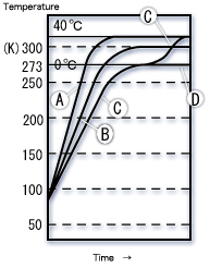 |
A:N2 Purge+Band Heater (with little water)
Shield and baffle are warmed to approx. 40℃. H20 is removed, and regeneration is well performed.
B:N2Purge(with little water)
The most common method. Regeneration is well performed with little water.
C:N2 Purge+Band Heater(Large amount of pumped H20)
Ice is melted down quickly by band heater although warm-up is temporally stopped during melting of ice.(Recommended for glass/plastic substrate.)
D:N2 Purge, or Natural Warm-up (Large amount of pumped H20)
Ice maintains icy state since this method cannot generate enough heat to melt it.
If the cryopump which still contains ice is rough pumped, its pumping capacity is lowered shortly. Special cautions are required for deposition of glass and plastic. Be sure that the electro motive force of K thermocouple is around 0mV. Be sure to use band heater in combination.
If large amount of H2O is expected, record the electro motive force of K thermocouple during regeneration to see its pattern. Also, check that the ice has melted completely.
(2)Rough Pumping
In general, a rotary pump is used as a roughing pump. When using a rotary pump, oil backflow is small at high pressure due to air viscous flow flushing action. However, rough pumping to approx. 15Pa or below, there is a danger of increased oil backflow due to lowered flushing action.
ULVAC CRYOGENICS guarantees cryopump performance at roughing pressure of 40Pa in normal use as a safety standard. It is recommended to use a foreline trap to rough pump below 20Pa. The use of zeolite trap requires special attentions for disadvantages such as extended roughing time, saturation in a short time with large amount of H2O, cause of dust, and periodical activation required.
When there is a large amount of water inside cryopump, water temperature drops because evaporative latent heat is removed with evaporation of water during rough pumping. In this case, water will linger in icy state and regeneration performed defectively. Therefore, it is important to keep water in a liquid state, not in an icy state, by heating with band heater during rough pumping. Also, when pumping a large amount of water with rotary pump, it may be impossible to rough pump to 40Pa by emulsifying oil. In general, there are several measures other than frequent oil change such as:
1)Use of large-rotary pump which contains more oil and has high capacity against water.
2)Use of rotary pump, which separates oil from water, with a drain.
3)Use of mechanical booster pump to lower ultimate pressure.
(However, be sure to change oil of the rotary pump periodically.)
For process of large amount of glass/plastic, countermeasures mentioned above should be taken in advance because large amount of water will be generated.
4-2:Options for Regeneration
Introduction of nitrogen and use of band heater increase efficiency of regeneration. At ULVAC CRYOGENICS, “Regeneration Gas Purge PR Unit” for introducing nitrogen, and “RBH Band Heater” as band heater for regeneration are available. Also, “Automatic Regeneration Control ARC Unit” as an automatic regeneration controller is available.
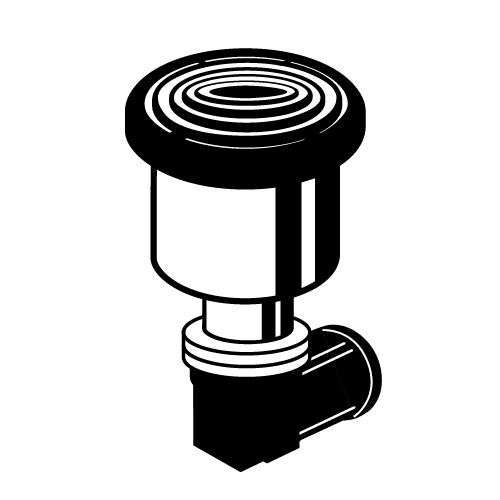
Figure 6:Regeneration Gas Purge PR Unit
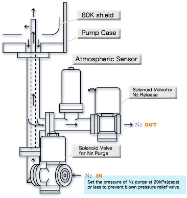
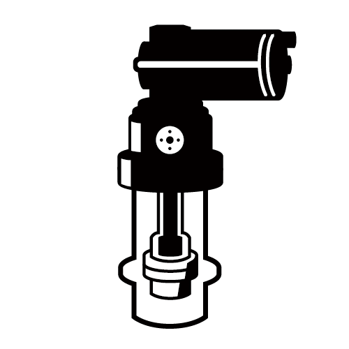
Figure 7:RBH Band Heater Figure 8:RBH Band Heater Power Consumption and Temperature Figure 8:RBH Band Heater Power Consumption and Temperature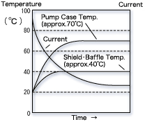 |
RBH Band Heater employs self controlled heater so that it can be operated without temperature controller. By controlling electric current with the heater resistance which increases as temperature increase, the heater stops heating and maintains the maximum set temperature. The temperature control system for RBH Band Heater is more reliable compared to bimetal thermostat since overheat caused by defect will not occur.
Please feel free to contact us about our product.
Our consultants will propose plans that fit your needs.